Question
I’m just getting started at measuring hearing aid directionality in my test box. Do you have an example of what such a measurement might look like?
Answer
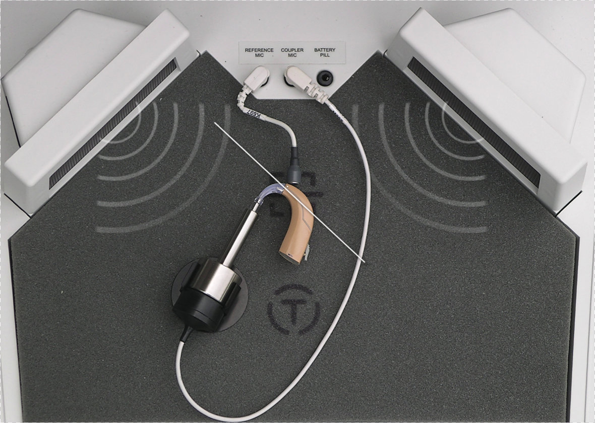
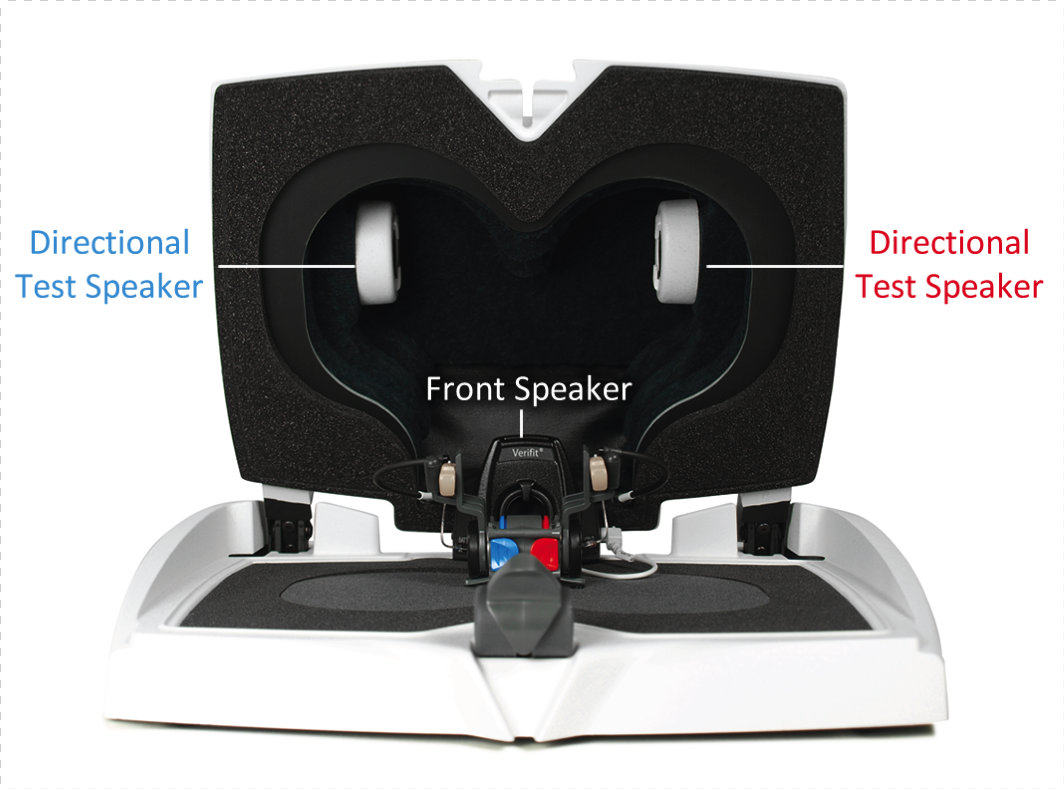
With Verifit technology (either Verifit or Verifit2), it is possible to generate simultaneous frequency response output curves for two input signals that are presented simultaneously from different directions. By orienting the hearing aid microphone ports in the test box so that one of the input signal speakers is front facing (0 degree azimuth), the other speaker will then occupy a secondary, or “jamming” input signal orientation. Figure 1 depicts the correct orientation of the hearing aid mic ports in a Verifit test box, and Figure 2 depicts the correct positioning of the hearing aid mic ports in a Verifit 2 test box (where the jamming speaker is in the lid of the test box as shown in Figure 3.)

Figure 1. Example of recommended hearing instrument positioning for BTE hearing instruments in the Verifit test box for directional testing.

Figure 2. Verifit2 test box showing location of test box speakers used for directional testing (front speaker, left jamming speaker, right jamming speaker).

Figure 3. Verifit2 test box showing location of test box speakers used for directional testing (front speaker, left jamming speaker, right jamming speaker).
There are two input signal options available: a Speech-Noise signal, where the front speaker output is speech and the jamming speaker output is noise; and a Noise-Noise signal, where only noise is presented from both speakers. Through a structured, alternating measurement paradigm, the aided output for front and back jamming speaker input signals can be measured and displayed independently. When these two output curves overlap, an omnidirectional condition is present. When these two curves separate, with the output for the back jamming signal less intense than the output for the front signal, a directional condition is present.
Video 1. Single View: Omnidirectional to directional.
In demonstration Video 1, the test box directional screen that you will see on your Verifit 2 equipment once you activate the directional mic test protocol is depicted. You click on one of the test buttons to start the directional test. This will activate a menu from which you can select both the stimulus type and level you wish to evaluate. In this example, a Noise-Noise test at 65 dB has been selected. The test begins with the hearing aid programmed in its omnidirectional mode. Note how the two measurement curves are overlapped in this omnidirectional condition, as one would expect. But when we activate the directional mic function through the hearing aid programming software, you can see immediately that the two measurement curves separate.
The thick curve (labeled F1) represents the output that is being recorded at the coupler microphone for the signal that is coming from the 0-degree azimuth (front) speaker in the test chamber. The second thin curve (labeled B1) represents the output for the signal that is coming from the back (jamming) speaker. These two curves separated substantially when the directional microphone capability was activated. We can clearly see that once the directional microphone has been activated, there is a significant favoring of output for signals coming from the front of the hearing instrument versus signals coming from the back/jamming direction.
While the measurement example in Video 1 was conducted with a single hearing instrument, you can also conduct simultaneous directional measurements of two hearing instruments in the Verifit2 test box (Note: directional testing can also be conducted on the patient’s ears as well). Simply connect the two hearing instruments to be evaluated to the binaural coupler microphones in the test box, select the dual view mode, click on the left/right link button, and generate the desired test signal as described previously. In this example, both hearing instruments are initially set to omnidirectional microphone mode (overlapping curves for both the left and right hearing aids) and then the directional microphone is engaged (separated curves for both the left and right hearing aids). The interpretation of the curves is done exactly the same as in the monaural case, however you are now able to evaluate the directional performance of both hearing aids, in real-time, at the same time. This is demonstrated in Video 2.
Video 2. Dual View: Omnidirectional to directional.
For a more detailed instruction on directional microphone measurements, please refer to the Audioscan course, The Verifit Directional Mic Test: Evaluating Modern Directional Microphone Technologies, that is available in text and recorded formats. For the latest information and resources from Audioscan, please visit www.audioscan.com or the Audioscan Expo Page on AudiologyOnline.

